Transistors
In the next page, we will start using programming to control LEDs. But we need to learn about one more component before we begin. It is called the transistor, and it has three legs.

One of the legs (the middle one) is called the base, and is used to control the amount of current flowing through the other two legs. You have to supply a small amount of current to the base to get current to flow. Here’s an illustration:

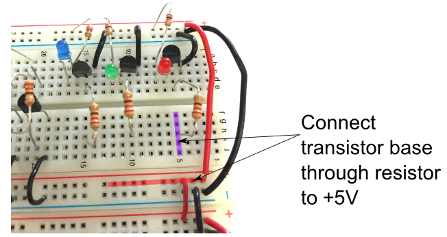
To make the second red LED (connected to a resistor and a transistor) light up, connect the base of the transistor to a high voltage through the resistor, as shown below.

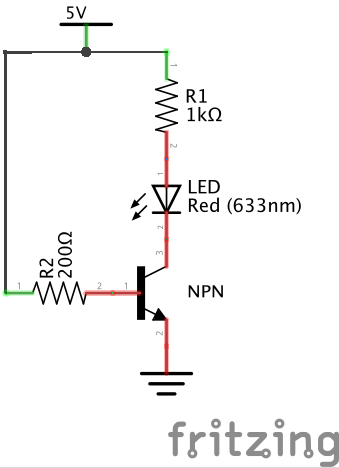
The circuit that you just made work is drawn like so:

Notice that even though the LED is connected to a high voltage, the circuit is not complete unless the transistor base is also connected to a high voltage. Supplying the base with a high voltage allows current to flow through the transistor, which in turn allows current to flow through the LED to the transistor collector, through the transistor emitter, to ground.
Look closely at the way the components are plugged into the breadboard, and compare to the schematic above. Can you trace the way current moves through the circuit? Look back at the breadboard internal connection image if needed.
CHECKPOINT!
We will always use transistors to control outputs with the Arduino (ok… we will also use one other kind of special chip, but it is basically made from transistors inside). That way, the Arduino only has to provide enough current for the base, which is very small compared to the current that may be demanded by different outputs. This will help to protect the Arduino.
