Motor Controller
Motor Controller Board Overview
You should have:
- a power supply breadboard (any of them will do)
- motors (CD drive and fan which we will scavenge from old computers)
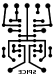
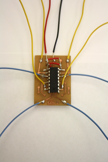
- a motor control board, which looks like this:
The Arduino boards can only control a small amount of current. The motor controller boards are a handy device for controlling the larger currents that some devices such as motors need. Each motor controller board can drive two motors independently in either direction.
Each motor controller board should have 10 wires: - two power wires (red, black) for the chip - two control wires (pair of yellow wires) for the first motor - two control wires for the second motor - two output wires (pair of blue wires) for the first motor - two output wires for the second motor.
The location of the wires is shown in the diagram below, but the leads should also be labelled appropriately.
You don’t have to use both motors; just keep the unwanted control and output wires disconnected.
How to Setup
- To set up the motor controller board, we first need to connect the power lines (red/V++ and black/ground) to the breadboard.
- Next, we hook up the control wires (yellow) to the Arduino output pins.
- Finally we hook up our motors up to the green wires.
To test the motor, upload the example Examples->SpicePinball->Pbmotorcontrol in the Arduino IDE.
How H-Bridges Work
This section isn’t needed to actually use the motor control boards, but it explains what’s going on inside.
[[hbridge image]]
The integrated circuit (a xxxx) contains two H-bridges. An H-bridge is a set of four transistors which allow current to be directed in either direction through the motor. In the image above, we can start the motor in one direction by turning on transistors A and D while keeping B and C turned off. We can then reverse the direction by turning on B and C while keeping A and D off. If we keep all the transistors off, the motor is in a “brake” state, since when the motor is spun it generates a voltage that attempts to drive the motor in the opposite direction of motion (slowing the motor down). Finally, if transistors A and B are off while C and D are on, the motor is in a “coast” state and the motor is free to rotate.
So, we have 4 possible states we can set the motor: brake, coast, forward, and backward.
Technical Note:
The motor control board were designed by Dileep Reddy.
The components for the PCB design are shown below:
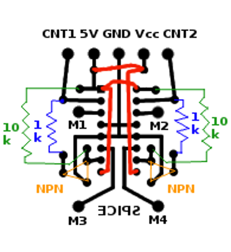
The corresponding PCB connection looks like this: