Proximity Sensor
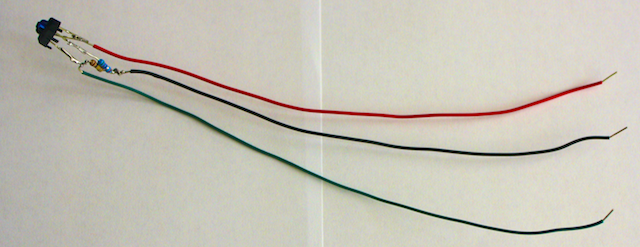
Another kind of analog input we can use is the proximity sensor. It is made of an infrared emitter and receiver, pointing in the same direction, with a wall between them. It looks like this:
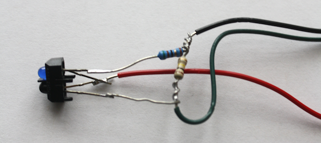
The emitter creates pulses of infrared light. When this infrared light reflects off of surfaces (your hand, a pinball), it is sent back to the receiver, which produces a small voltage. The resistors soldered to the setup are arranged such that the output signal read on the green wire is between 5V and 0V. The red wire on the sensor will connect to 5V, and the black wire to 0V.
This sensor is very easy to set up. First, make sure the red and black wires from the proximity (infrared) sensor goes to +5V and ground. Connect the green wire to an analog input on the Arduino.
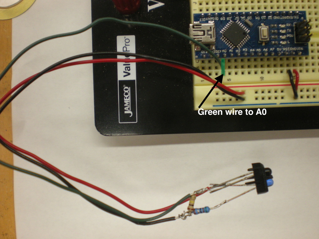
The signal produced by the proximity sensor is largest (near 5V) for objects held near the detector, and falls off to 0V as objects are moved farther away.
Technical Note:
These detectors use a standard interrupt circuit
Both the IR interrupts and the IR reflection detectors are essentially an IR emitter-detector pair. The IR (infrared) LED will typically have a rated current of 15 mA, and hence will require current limiting resistor of around 300 Ohms on the emitter Anode (+) side. The detector functions like an NPN transistor with the base terminal being activated with the IR signal. The resistor on its collector terminal can be 1K or 10K. The emitter resistor is determined by the current budget, and the detector resistor can be tweaked for sensitivity.