A Better Piezo
Here, we’ll show you how to use the piezo as an analog sensor in a more accurate way. This activity is optional, but it describes a way to use the piezo sensors more accurately.
The little board with a circuit on it that you have been given for this is called a “breakout board” (That term describes any little circuit board that has circuitry useful for using external things (such as piezos!) with microcontrollers). The circuit on the board is called a peak detector circuit (you’ll see why in a bit), which has been slightly modified to work the way we want it to with the Arduinos.
The signal of a piezo will always look something like this:
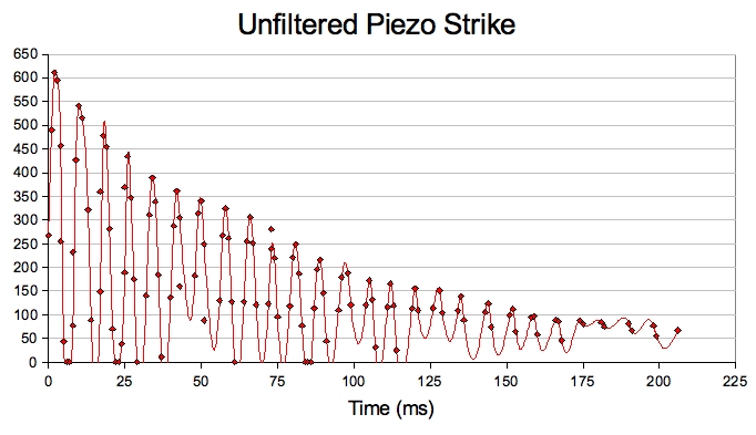
The maximum height of a piezo signal is proportional to how hard the piezo is struck. When the piezo is struck, the circuit on the breakout board will output a signal that climbs to the peak value of the piezo’s signal, then it will drop off, which is why it’s called a peak detector. This signal is more predictable and steadier than the messy signal of a raw piezo, so using this circuit will reduce the number of piezo events that the Arduino “misses” due to the timing of the piezo signal, and increase the reliability of using thresholds to measure how hard the piezo was struck!
To use the piezo and breakout board, first connect the wires on the breakout board in the following way:
- “PIn” to the red wire of the piezo
- “PGnd” to the black wire of the piezo
- “GND” to the ground rail on your breadboard
- “RST” to an available digital pin on your Arduino
- “5V” to the +5V rail on your breadboard
- “AOut” to an available ADC pin on your Arduino (A0 - A7)
Open the sketch peak_piezo from the “Sounds and Senses” sketchbook and upload it to the Arduino. Next, open the serial monitor. Now rest the gold side of your piezo on a flat surface (with the wires facing up) and tap on the white part of the piezo while watching the serial monitor.
What values do you get if you tap it lightly? How about if you tap it harder?
Try tapping it with the same amount of pressure between taps and see what values you get. You should also try pressing the piezo against the table with a couple fingers on the gold edge while tapping the white area with another finger. Try tapping it with the same pressure again. Notice how securing it like that makes it so that you get more consistent values.
In the sketch, the threshold argument to mypiezo will set a limit on how large piezo signals must be before your Arduino will accept them. The peak capture time argument is the amount of time that your Arduino will wait before it measures and reports the piezo’s signal after it has received a signal that has surpassed the threshold. The reset hold time argument is how long your Arduino will wait before it will accept another piezo signal.
Here’s an illustration of what the last three arguments to mypiezo correspond to:
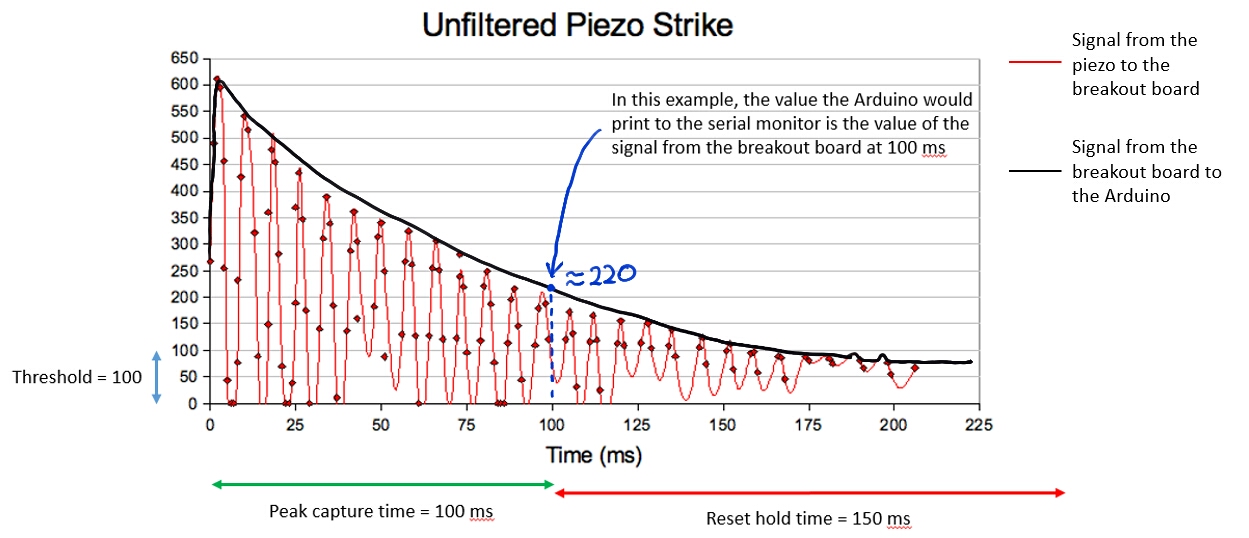
The values for the last three arguments that are already in the sketch were chosen so that the Arduino will consistently report a single measurement per tap/vibration, which makes it a more effective analog amplitude sensor, whereas additional values are not necessary if you just wish to use it as an analog amplitude sensor. You can change these values to make your piezo perform a little differently.
Try changing the reset hold time to 10 ms. Then tap the piezo and see what happens to the values that get reported. Then try it with the peak capture time set to 10 ms and the reset hold time back at 150 ms, and see what changes. Finally, try setting both values to 10 ms, or 50 ms, and see what happens.
You may have to experiment with these values after installing the piezo on your pinball table to make it work the way you want it to given where it’s placed.
FYI: The peak detection that we used the breakout board circuit for can also be done by using a program that records the signal from a piezo connected straight to the Arduino and finds the largest value recorded from the signal. However, using the circuit allows us to save memory on our very memory-limited Arduino Nanos for other stuff. So if you do something like this later with a microcontroller that has more memory, you don’t have to worry about building extra circuits!