Many shift registers
In all the previous programs, we have declared our byte variable with
the number 1 inside square brackets at the end (byte serdata[1];).
This is telling the Arduino that the variable serdata stores 1 byte. This is also counted from 0. So it is actually byte number 0. It can be called by using serdata[0], as we have done.
We only use it to store 1 byte because we only needed 1 byte for 1 shift register. On your breadboard, you will see a second shift register connected to the blue LEDs.
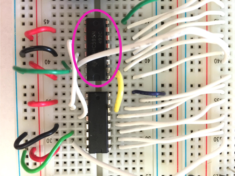
This second shift register’s clock and latch pins have been shared with the first. But its data pin is right now going to ground (0 volts). Try removing that connection, and instead connect the second shift register’s data pin to the first shift register’s QH’ pin:
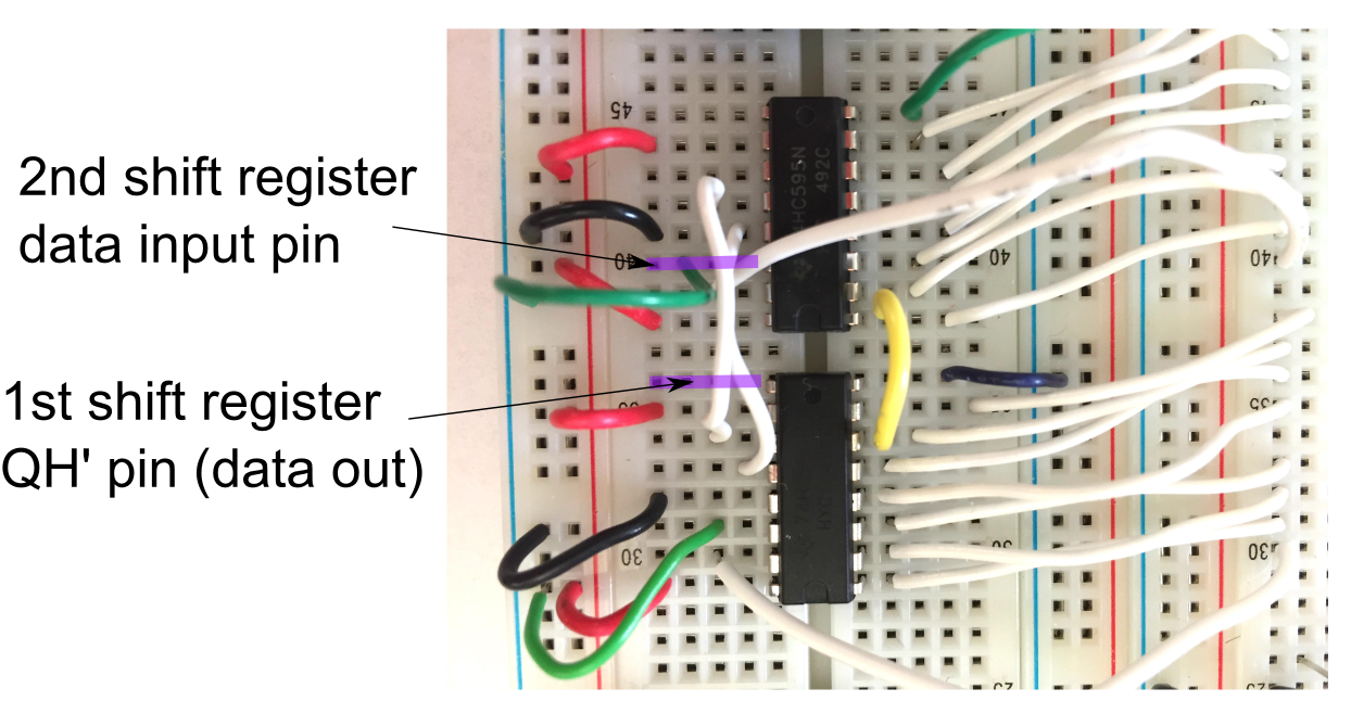
Now, as soon as the first shift register receives a new byte, it should shift its old byte to the new shift register, which is further down the line. Verify this.
CHECKPOINT!
Now try uploading the two-shreg sketch.
In this new program, we set numreg to 2, since we want to use
two shift registers with the object shregs. We also store 2
bytes in byte serdata[2];. This way, calling shregs.update(serdata); will shift out both bytes.
The two bytes of serdata can be called individually as:
serdata[0] = 0b00000000;
serdata[1] = 0b00000000;
as we do inside setup().
Take a look at the new changeserdata(int ff) function, and see
how the LED pattern is being generated. Try changing the code so the
bits are running away from each other instead of towards each other.
Did you do this by changing the serdata entries, or changing how
the flag changes?
CHECKPOINT!
In this way, you can connect as many shift registers you want, using just 4 pins on your Arduino. The shift registers don’t have to only control LEDs. They can control any digital component, as long as you remember to use them with transistors.