RGB LED
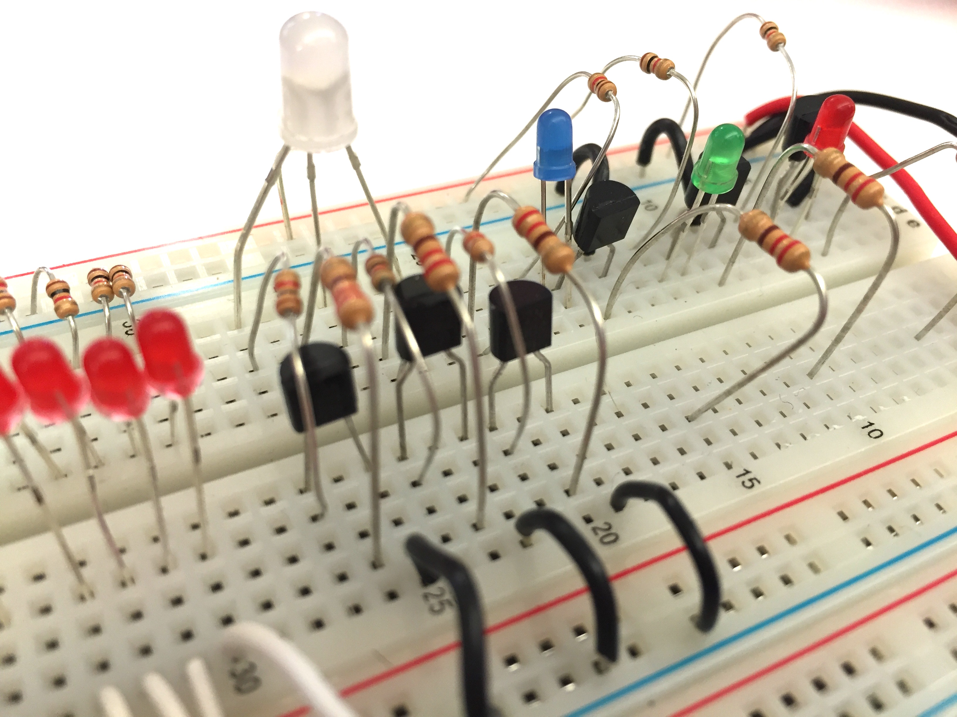
Now we will control the RGB LED. RGB stands for Red, Green, and Blue. The RGB LED is really three LEDs in one casing. An RGB LED has four legs. One of the legs (the longest one) goes to +5 volts, and the other three are used to control the three colors. This figure shows the transistors and resistors connecting to each LED within the RGB LED.
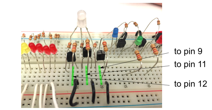
Use your jumper wires to connect the three RGB transistor bases to pins 12, 11, and 9.
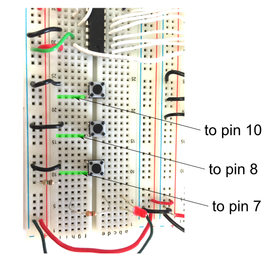
Also connect the three buttons to pins 10, 8, and 7 as shown.
Now open and upload the rgb-led program.
Try pushing the buttons, and see what they do. Bring an instructor around to confirm that your wires are right - the LED behavior will be the telling sign.
CHECKPOINT!
You will notice that the buttons that control the Red and the Green colors behave slightly differently from the one that controls the Blue color. We will explore that later.
Take a look at the program. Notice that there are plenty of grey lines that have been commented out by using the // symbol. The // symbol makes everything in that line that comes after it into a comment, so it won’t get uploaded into the microcontroller.
In this program, the comments have been made to help you make sense of the program. You can add your own comments as well.
Every line before the setup() function should look familiar to you, except the one that says:
Pb_switch bluesw(200);
We will get to that later.
Everything inside the setup() function should also be familiar. Use the comments as a guide to figure out what’s going on inside setup().
Inside the loop() function, there are two if-else structures for the Red and Green colors, that look exactly like the one in the buttons program.
Do you see exactly how the Red and Green if-else structures are working?