Breadboards
That white/yellow board with holes is called a breadboard.
A breadboard is used to quickly make and test circuits. We built some breadboards ahead of time for this session, with components already plugged in.
The holes on the breadboard have stripes of metal inside them like so:
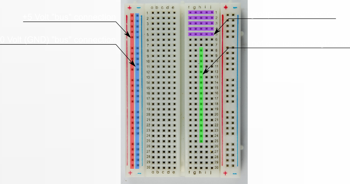
We can use these stripes of metal to make connections between our components. The red line holes are kept at 5 volts, and the blue-line holes are kept at 0 volts (0 volts is also called ground, sometimes shortened to GND). Those lines are convenient ways to connect to power from any point on the board without requiring many long wires.
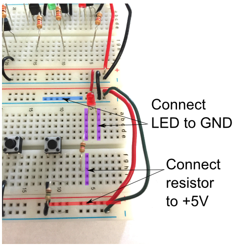
In the picture below, the smaller sets of holes are connected in direction of the the purple highlight. The short leg of the LED connects to ground through the black wire, and the long leg of the LED connects to the resistor. If you want to take out the LED to double-check which leg is long and which short, go ahead.
Make sure that your “wall wart” power supply (the black box power supply) is plugged into the power supply chip on the breadboard and into the wall.
Using a jumper wire, connect the 5 volt line (shown highlighted in red) to the end of the resistor as shown to complete the circuit, which will make the LED glow.
CHECKPOINT!